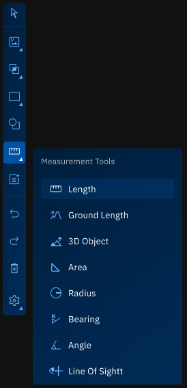
Measurement Tools
The Measurement Tools consists of tools that enable you to measure a number of different things:
- Lenght
- Ground Lenght
- 3D Object
- Area
- Radius
- Bearing
- Angle
- Line of Sight
Measure Length Tool
The Measure Length tool is used to calculate the straight-line distance between two points on the map. This measurement represents the shortest linear path over a flat surface, without accounting for terrain elevation.
This tool is ideal for quick, planar measurements between two locations.
Prerequisites
- Open a workspace with any visible map.
Use Cases
The Measure Length tool is useful in scenarios where accurate, straight-line distances are required:
| Use Case | Description |
|---|---|
| Distance Estimation | Quickly calculate direct distances between two geographic points. |
| Site Planning | Measure spacing between infrastructure elements like roads, fences, or plots. |
| Navigation Checks | Validate the shortest path between two fixed locations. |
| Construction Layout | Plan straight sections of pipelines, roads, or utility lines. |
Using Measure Length Tool
In this section, you will learn how to use the Measure Length tool.
To use the Measure Length tool, do this:
-
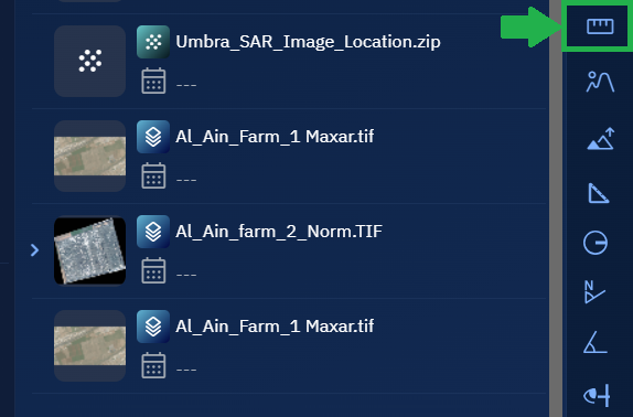
Go to the Analyst Tools panel, click Measure Length tool.
The Measurements dialog box is displayed.
-
On the Measurements dialog box, click the Measure Units drop-down list to select one of the following units of measurement:
- Meters
- Kilometers
- Feet
- Miles
- Nautical Miles
This unit determines how the distance will be displayed after the measurement is drawn.
-
Locate a layer in the Layers section, click the vertical three-dots menu, and then select the Zoom into Layer option.
-
Click on the map to set the start point, draw the line, and double-click to set the end point.
The system will now draw a straight line between the two points.
- Viewing the measurement on the Measurements dialog box and interpret the result.
- The value shown is the straight-line (planar) distance between the selected points.
Reviewing and Manage Length Measurements
After drawing a line, the Measurements dialog box will display the measured distance next to the line — for example: 25.76 m.
If you draw multiple lines, each measurement will be listed separately. For each entry, the following options are available:
| Button | Description |
|---|---|
| Delete | Click to remove the corresponding line and its measurement from the map. |
| Copy | Click to copy the precise measurement value (e.g., 25.755476260316254) to a clipboard or notepad. |
Measure Ground Length Tool
The Measure Ground Length tool is used to measure the actual distance along the terrain surface between two points on the map. Unlike a straight-line (planar) distance, this tool considers elevation data to calculate the true ground distance, taking into account slopes, curves, and surface undulations.
Prerequisites
- Open a workspace with any visible map layer.
Use Cases
The Measure Ground Length tool is useful in the following scenarios:
| Use Case | Description |
|---|---|
| Infrastructure Planning | Calculate realistic cable, pipeline, or road lengths over uneven terrain. |
| Topographic Analysis | Assess distances across hills, valleys, or ridgelines using elevation profiles. |
| Field Operation Planning | Estimate actual walking or driving distance across ground-level terrain. |
| Environmental Studies | Measure lengths of natural features such as rivers or fault lines. |
Using Measure Ground Length Tool
In this section, you will learn how to use the Measure Ground Length tool.
To use the Measure Ground Length tool, do this:
-
Go to the Analyst Tools panel, click Measure Ground Length tool.
The Measurements dialog box is displayed.
-
On the Measurements dialog box, click the Measure Units drop-down list to select one of the following units of measurement:
- Meters
- Kilometers
- Feet
- Miles
- Nautical Miles
This unit determines how the distance will be displayed after the measurement is drawn.
-
Locate a layer in the Layers section, click the vertical three-dots menu, and then select the Zoom into Layer option.
-
Click on the map to set the start point, draw the line, and double-click to set the end point.
The system displays a line that follows the terrain surface between the two points.
- Viewing the measurement on the Measurements dialog box and interpret the result:
- The value represents the true ground distance, taking terrain elevation into account.
Reviewing and Manage Ground Length Measurements
After drawing a line, the Measurements dialog box will display the measured distance next to the line — for example: 42.83 m.
If you draw multiple lines, each measurement will be listed separately. For each entry, the following options are available:
| Button | Description |
|---|---|
| Delete | Click to remove the corresponding line and its measurement from the map. |
| Copy | Click to copy the precise measurement value (e.g., 42.8293610028367) to a clipboard or notepad. |
Measure 3D Objects Tool
The Measure 3D Objects tool is used to measure the dimensions of 3D objects displayed on the map, such as buildings or terrain features. This tool allows you to interactively capture vertical and horizontal measurements from 3D data visualized in the workspace.
Prerequisites
- A 3D Tiles layer must be loaded in the workspace. This layer provides the elevation and structure data needed for 3D measurements.
Use Cases
The Measure 3D Objects tool can be used in various geospatial and infrastructure applications:
| Use Case | Description |
|---|---|
| Building Height Estimation | Measure the height of buildings or towers using elevation data. |
| Terrain Feature Analysis | Determine elevation differences in terrain, such as cliffs, hills, or embankments. |
| Urban Planning | Assess vertical clearances or spatial gaps between 3D structures. |
| Infrastructure Validation | Validate physical structure dimensions against design specifications. |
Using Measure 3D Objects Tool
In this section, you will learn how to use the Measure 3D Objects tool.
To use the Measure 3D Objects tool, do this:
-
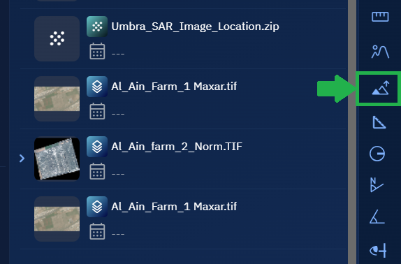
Go to the Analyst Tools panel, click Measure 3D Objects tool.

The Measurements dialog box is displayed.
-
On the Measurements dialog box, click the Measure Units drop-down list to select one of the following units of measurement:
- Meters
- Kilometers
- Feet
- Miles
- Nautical Miles
This unit determines how the measurement result will be displayed.
-
Locate a layer in the Layers section, click the vertical three-dots menu, and then select the Zoom into Layer option.
-
Click on a 3D object on the map to set the start point. Move the cursor to the end point, and double-click to complete the measurement.
The system will now display a measurement line on the selected 3D object.
-
Viewing the result on the Measurements dialog box:
- The measured value is shown in the selected unit next to the line.
- Use this to assess dimensions or height differences across 3D features.
Reviewing and Manage 3D Measurements
After drawing a measurement, the Measurements dialog box will display the measured value — for example: 123.37 m / 19.93 m / 12.2 m.
If you draw multiple measurements, each will be listed separately. For each entry, the following options are available:
| Button | Description |
|---|---|
| Delete | Click to remove the corresponding measurement and line from the map. |
| Copy | Click to copy the precise measurement value (e.g., 23.37 m / 19.93 m / 12.2 m) to a clipboard or notepad. |
Measure Area Tool
The Measure Area tool is used to measure the total area enclosed within a drawn region on the map. The measurement is calculated in the selected unit based on the shape drawn.
Prerequisites
- Open a workspace with any visible map layer.
Use Cases
The Measure Area tool is commonly used in spatial planning, environmental analysis, and land use assessment:
| Use Case | Description |
|---|---|
| Land Use Analysis | Measure the area of agricultural plots, urban zones, or forest coverage. |
| Environmental Impact Studies | Determine the extent of wetlands, water bodies, or conservation regions. |
| Urban Planning | Evaluate building footprints, green space allocation, or zoning boundaries. |
| Disaster Assessment | Measure flooded or burned regions to quantify affected zones. |
Using Measure Area Tool
In this section, you will learn how to use the Measure Area tool.
To use the Measure Area tool, do this:
-
Go to the Analyst Tools panel, and click the Measure Area tool.
The Measurements dialog box is displayed.
- On the Measurements dialog box, click the Measure Units drop-down list to select one of the following units of measurement:
- Meters
- Kilometers
- Feet
- Miles
- Nautical Miles
This unit determines how the area will be displayed after the region is drawn.
-
Locate a layer in the Layers section, click the vertical three-dots menu, and then select the Zoom into Layer option.
-
Click on the map to start drawing a polygon:
- Click point A to start.
- Click additional points (B, C, etc.) to define the region.
- Double-click the final point (for example, D) to complete and close the area.
The system will automatically calculate the enclosed area and display it on the screen.
-
Viewing the result on the Measurements dialog box.
The measured area is displayed in your selected unit. You can draw multiple areas and manage them individually.
Reviewing and Manage Area Measurements
After drawing a region, the Measurements dialog box will display the measured area — for example: 5,432.76 sq.m.
If you draw multiple area measurements, each will be listed separately. For each entry, the following options are available:
| Button | Description |
|---|---|
| Delete | Click to remove the corresponding shape and its measurement from the map. |
| Copy | Click to copy the precise area value (e.g., 5432.7612341) to a clipboard or notepad. |
Measure Radius Tool
The Measure Radius tool is used to measure the radius (distance from the center to the edge) of a circular area on the map. This tool is useful for visualizing proximity zones or spatial buffers around a defined central location.
Prerequisites
Open a workspace with any visible map layer.
Use Cases
The Measure Radius tool is commonly used in location-based analysis workflows:
| Use Case | Description |
|---|---|
| Proximity Analysis | Visualize coverage areas around points of interest such as schools or hospitals. |
| Emergency Planning | Define buffer zones for hazard containment or response radius. |
| Retail and Service Planning | Assess customer reach or walkability radius around stores. |
| Urban Planning | Analyze zoning impacts within fixed-distance circles. |
Using the Measure Radius Tool
In this section, you will learn how to use the Measure Radius tool.
To use the Measure Radius tool, do this:
-
Go to the Analyst Tools panel, and click the Measure Radius tool.
The Measurements dialog box is displayed.
- On the Measurements dialog box, click the Measure Units drop-down list to select one of the following units of measurement:
- Meters
- Kilometers
- Feet
- Miles
- Nautical Miles
This unit determines how the radius will be displayed after the measurement is drawn.
-
Click on the map to set the center point of the radius.
-
Hold and drag outward to define the radius size. Release the mouse to complete the circle.
A circular area is drawn on the map with the radius measured from the center to the outer edge and displayed on the screen.
-
Viewing the measurement in the Measurements dialog box.
The radius is displayed in the unit you selected. Multiple radius measurements can be added and managed from the same dialog box.
Reviewing and Manage Radius Measurements
After drawing a radius, the Measurements dialog box will display the measured radius — for example: 100.00 m.
If you draw multiple radius measurements, each will be listed separately. For each entry, the following options are available:
| Button | Description |
|---|---|
| Delete | Click to remove the corresponding circle and its measurement from the map. |
| Copy | Click to copy the precise radius value (e.g., 100.000238) to a clipboard or notepad. |
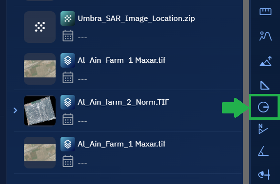
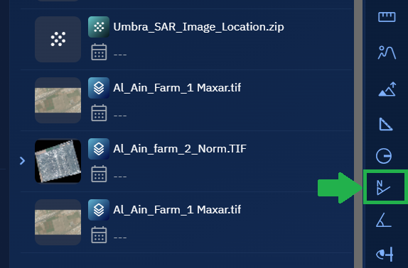
Measure Bearing Tool
The Measure Bearing tool is used to determine the direction or angle between two points relative to the geographic North. The result is displayed in degrees (°), measured clockwise from the North direction.
Prerequisites
Open a workspace with any visible map layer.
Use Cases
The Measure Bearing tool can be used in a variety of navigation and planning workflows:
| Use Case | Description |
|---|---|
| Navigation and Routing | Determine the direction between two locations for planning travel routes. |
| Surveying and Fieldwork | Measure directional bearings for ground-level survey points. |
| Military and Tactical Ops | Calculate angles for strategic movement and orientation relative to North. |
| Environmental Monitoring | Align sensor setups and equipment facing a specific directional bearing. |
Using Measure Bearing Tool
In this section, you will learn how to use the Measure Bearing tool.
To use the Measure Bearing tool, do the following:
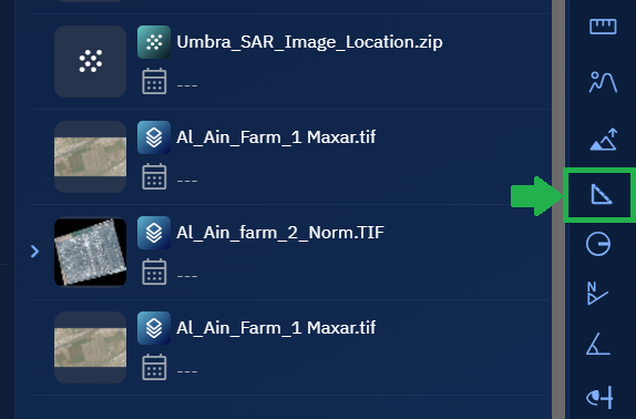
- Go to the Analyst Tools panel, and click the Measure Bearing tool.
The Measurements dialog box is displayed.
-
Click on the map to set the starting point.
-
Click again to set the ending point.
The system draws a line between the two points and calculates the bearing direction in degrees (°) from North.
-
Viewing the bearing result on the Measurements dialog box. The bearing angle will appear next to the measurement line.
Bearings are always measured clockwise from the geographic North.
Reviewing and Manage Bearing Measurements
After drawing a line, the Measurements dialog box will display the measured bearing — for example: 72.58°E.
If you draw multiple bearing measurements, each will be listed separately. For each entry, the following options are available:
| Button | Description |
|---|---|
| Delete | Click to remove the corresponding line and its measurement from the map. |
| Copy | Click to copy the precise measurement value (e.g., 72.582994137) to a clipboard or notepad. |
Measure Angle
The Measure Angle tool is used to determine the angle between two intersecting lines on the map. The angle is calculated in degrees (°) and displayed in the Measurements dialog box.
This tool is useful for analyzing spatial relationships and angular deviation between features such as roads, buildings, slopes, and more.
Prerequisites
- Open a layer with any source data
Use Cases
The Measure Angle tool is helpful in several geospatial analysis scenarios:
| Use Case | Description |
|---|---|
| Infrastructure Planning | Measure angular deviation between roads, pipelines, or planned structures. |
| Urban Design | Analyze street intersections, building orientations, or zoning angles. |
Using Measure Angle Tool
In this section, you will learn how to use the Measure Angle tool.
To use the Measure Angle tool, do the following:
- Go to the Analyst Tools panel, and click the Measure Angle tool.

The Measurements dialog box is displayed.
-
Locate a layer in which you want to measure angles.
-
Click on point A to set the starting point. Then click on point B to draw the first segment (line AB). Move the cursor to point C and double-click to complete the second segment (line BC). The system will calculate and display the angle formed at intersection point B between the two lines.
The angle value is displayed on the screen.
-
Viewing the calculated angle in degrees (°) in the Measurements dialog box. Measurements are also displayed on the screen.
The angle value is displayed next to the measurement line.
Reviewing and Manage Angle Measurements
After drawing an angle, the Measurements dialog box displays the measured angle — for example: 47.32°.
If you draw multiple angle measurements, each will be listed separately. For each entry, the following options are available:
| Button | Description |
|---|---|
| Delete | Click to remove the corresponding angle and its measurement from the map. |
| Copy | Click to copy the precise angle value (e.g., 47.321834652) to a clipboard or notepad. |
Line of Sight Tool
The Line of Sight tool measures the straight, unobstructed distance between two points on a 3D surface. It helps determine whether there is a clear view (line of sight) between a starting location and a destination point, based on elevation data.
Prerequisites
Before you use the Line of Sight tool, ensure that a 3D Tiles layer with elevation data is loaded in your workspace.
- Open a workspace and load at least one 3D Tiles layer.
- To confirm the layer is loaded, check the Layers List panel. The 3D Tiles file should appear there.
If 3D Tiles layer is NOT loaded, the tool will still function but it will display a red line—even if there are no obstructions—because the elevation data needed for visibility analysis is missing.
Use Cases
The Line of Sight tool is valuable in a wide range of geospatial analysis scenarios where visibility between two locations is critical. Below are some common use cases:
| Use Case | Description |
|---|---|
| Surveillance and Security Planning | Assess if observation towers or cameras have a direct line of sight to areas of interest. |
| Urban Development and Zoning | Evaluate how new structures (e.g., buildings, towers) may block views or interfere with sight lines. |
| Telecommunication Planning | Determine optimal placement of antennas or communication towers for unobstructed signal paths. |
| Emergency Response Planning | Ensure line-of-sight visibility between command centers and critical field locations. |
| Military or Tactical Analysis | Simulate lines of sight for strategic positioning, targeting, or defense planning. |
| Environmental Monitoring | Check if sensors or observation stations have visibility over target areas (e.g., forests, coastlines). |
Using Line of Sight Tool
In this section, you will learn how to use the line of sight tool.
To use the line of sight tool, do this:
-
Go to the Analyst Tools panel, click Line of Sight tool.
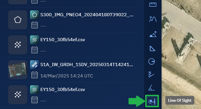
The Measurements dialog box is displayed.
-
On the Measurements dialog box, click the Measure Units drop-down list to select one of the following units of measurement:
- Meters
- Kilometers
- Feet
- Miles
- Nautical Miles
This unit determines how the distance will be displayed after the measurement is drawn.
-
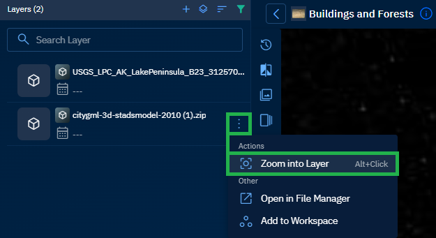
Locate a layer with 3D tiles data in the Layers section, click the vertical three-dots menu, and then select the Zoom into Layer option.
-
Press and hold the Ctrl key and move your mouse up or down to tilt the map. Zoom in or out using the mouse scroll to view the 3D details on the map.
Tilting the view helps you to visualize the 3D terrain and elevation details. This step is essential for using the Line of Sight tool effectively.
-
Click on the map to set the start point, draw the line, and double-click to set the end point.
The system will now draw a line between the two points.
-
Viewing the measurement on the Measurements dialog box and interpret the result:
- A green line indicates a clear line of sight — no obstructions between the points.
- A red line means the view is blocked.
Reviewing and Manage Line Measurements
After drawing a line, the Line of Sight dialog box will display the measured distance next to the line — for example: 25.76 m.
If you draw multiple lines, each measurement will be listed separately.
For each entry, the following options are available:
| Button | Description |
|---|---|
| Delete | Click to remove the corresponding line and its measurement from the map. |
| Copy | Click to copy the precise measurement value (e.g., 25.755476260316254) to a clipboard or notepad. |
This tool allows you to easily manage, compare, or document multiple line of sight measurements as needed.